Was back in February I sprayed the Polybrush and Polyspray coats and began to have problems with contamination..

The initial problem was traced to the tack cloths I was using. I usually just use the yellow ones from the local paint store, but I thought I'd "treat" myself to some "Boeing approved" versions. Anyway back to the cheaper yellow ones....
I carefully prepared the tailfeathers and a few small parts for top-coat. The paint went on ok and looked good.
The next day I couldn't believe what I was looking at. No trace of the tack cloth problem but still far too many specs and in localized areas, craters/fisheye or whatever you want to call it when the paint flows away from a tiny pin-head size circle.
I immediately assumed it was my equipment ie bad air, bad filters, bad hoses etc. So set about fixing all of that. No problems found but I went through it all anyway. I called Polyfiber and they were very helpful. The suspect... not waiting long enough between prep wiping with C2210 and applying topcoat. Further discussions with people in the know suggested using an alcohol based cleaner was the way to go.
I've also washed my paint "booth" from top to bottom, sealed off every potential leak, and installed new finer filter elements. By the time all of this was done I was well past the 72-hour timeline for re-coating and the tailfeathers needed to be wet sanded anyway to remove the blemishes. I've yet to get back to painting as I've been concentrating on fabricating parts....

Christmas 2015
Finishing tapes were applied to the tail feathers and fuselage concurrently. Its good to have a couple of things on the go rather than waiting for glue to dry. It basically kept me from being too eager with the iron (which works better if the Poly Brush is dry).


I took the time to make a couple of 2" straightedges out of some odd pieces of plexiglass I had. Makes short work of marking out rib tapes.


This at least enabled avoiding the use of bias tape as much as possible. Bias tape pinks unravel easily.


A method of getting a good butt joint is to trace the tape below with the soft pencil.
Usually enough of a shadow can be picked up to provide a guide for the pinking shears.

The stabalizer rib tapes are butted. Seemed like a reasonable way to do it.

Trailing edge tape goes on first on the stab (after the rib tapes of course).

I tried to heat form a straight tape but couldn't make it work, so I used bias for the tip and straight for the remainder.


Corners are finished with butt joints.

With both stabs done except for drain grommets I turned my attention to the elevators.
 Access to the trim mechanism is needed along with the opening for the pushrod.
The pushrod opening is the same as the rudder cable openings on the fuselage.

These will aid in trim servicing if the belcrank needs to be removed for any reason, but will be left closed unless needed.

So, in place of applying Poly Brush first and then fighting time and the tape, I attached the inboard end, once dry I pull the tape into position, taking my time and lining it up perfectly with the right amount of tension to achieve the correct width. Clamps are used to hold the tape in position and snug against the tube.


Poly Fiber stresses laying tapes into wet Poly Brush, but also says, in regard to rib tapes, that as long as the outer portions of the tapes are well attached your good. So I applied the same reasoning to the bias tape (and the centre of the tape is well stuck anyway) for a much better way of applying bias tapes imo.
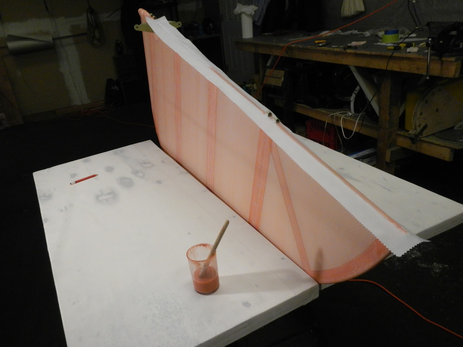
With all the doilies, tapes and gussets installed, drain grommets are added and yet more time is spent with the iron, smoothing out lumps and bumps and making sure things are stuck.
Tail feathers are ready for spraying.
October 2015
The tail surfaces seem to be a good place to start the covering adventure and fresh from attending the Polyfibre workshop at Oshkosh I felt primed and ready.

I won't regurgitate the Polyfibre manual, rather I'll point out some things that I found work and some details that are not in the manual.
At the OSH workshop we covered a mock stabilizer which had no hinges or other obstacles that make things a little more complicated.
Remember to apply the anti-chafe tape cuz it's no fun having to un-glue the fabric (only made this mistake once so far!)
 Cut the fabric with lots of extra (only made this mistake once so far too)
Fold the panel in half and crease. This provides a good starting point and makes it easy to mark and cut the hinge locations.

The manual talks about using a razor blade to trim the excess fabric. I prefer to form the fabric first, mark all my cuts with a pencil, paint them with fabric adhesive,

Forming the curved edges is about trying to shrink the fabric in one direction only, so there needs to be enough extra to keep good tension on the fabric as the iron is applied.

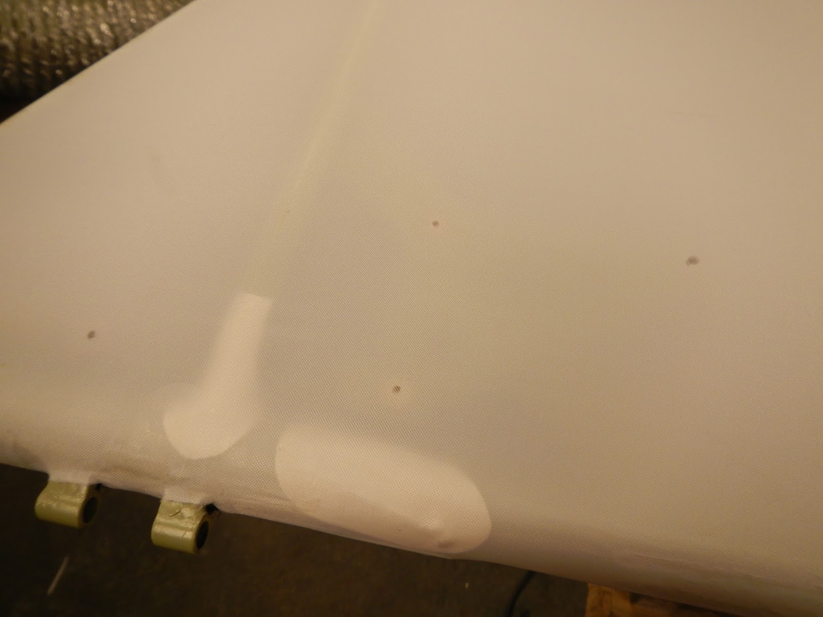
In one place the manual says you don't need to glue the leading edge when the fabric is one piece top and bottom. Then in the next paragraph it says to glue. Anyway at OSH we glued. This allows the bottom fabric to be shrunk at 250. Then to get the required overlap a pencil line is drawn. The top fabric is then heat formed as required and the pencil line is visible through the fabric. Excess is then trimmed and the fabric is glued. The edge of the top fabric is glued to the pencil line (even if it causes wrinkles along the edge...which are removed later with the iron). This procedure renders a nice straight edge.

There is minimal room for the trim bellcrank in the elevator, Mine was installed with AN3 bolts with 75% of the heads shaved off. This time it's installed using clevis pins which have a much lower profile and the same hardness specification as AN3 bolts.


Once the fabric is shrunk to the final 350 degrees, I transfer and mark the coordinates.
 The rudder must be covered in two pieces because of the control horns
The smell and need for fast but smooth brush strokes bought back memories of my first ever airplane covering project... a Sterling Ringmaster, a glo-engine powered control line model airplane my father and I built when I was perhaps 5 or 6 years old


Next up is rib lacing


Keep on lacing....
March 2015
One thing that can be done in the cold is welding. I expect, when the weather finally warms up, I'll be glad I did most of the welding tasks in February.
First up was the left stabilizer. It was serviceable, but at some point someone had done an external sleeve repair on the leading edge. Clearly visible it was something that always bothered me so a new leading edge tube was the order of the day(s)
Now the leading edge is 7/8" chromoly and it really really wants to stay straight! I concluded that even if I could find a tube bender for this size tubing locally, it would probably be of the type that "allows" some deformation. So.... I set about building one. There was a good deal of trial and error but my only regret is that I didn't video the machine in action, it worked so well!

 The
leading edge is bent to the exact shape of existing before dismantling
The
leading edge is bent to the exact shape of existing before dismantling
Both ends
are left long until final fitting

The
existing stab is blocked up on a flat work top. Unfortunately I don't have
a steel table, but at least it's easy to attach blocks.
Also use a
sharpie to trace the outline of all parts. A simple way to double check
that things go back together right

The leading
edge is cut off
Leaving all
the rib material and some of the old tube.

Each weld is carefully trimmed
back, leaving the part as it was before it was originally assembled

Tip
is cut and gradually trimmed for a good fit

Ready
for tacking

After
tacking, the fuselage is needed to check fit
Several checks to make sure things are straight. Here fishing line is strung from tip to tip to help make sure I get the stab attach bolt holes in the right place.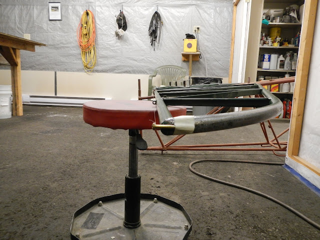


Next up,
both elevators needed work

The
left elevator had apparently been tweeked so I copied the tip bow shape from
the right elevator which looked undamaged. Anyway this will ensure both
elevators are the same shape.

Right
elevator is laid out in the same manner for replacement of the leading edge and
most of the trailing edge

The inboard
end of each elevator has a .050" sleeve. 1" O/D tube is cut
along its length and the fishmouth such that once clamped to the leading edge
there is a 1/8" gap.
The sleeve is welded together and to the base
tube at the same time.

Note that
the elevator trailing edge doesn't lay flat on the table. The shorter the
chord the closer the centreline of the trialing edge is to to the c/l of the
leading edge. The drill bits taped to the table are lifting the trailing
edge the calculated amount.
The
objective is to get things as close as possible on the table. After
things cool down, final adjustments are made by cold forming.

I was
a fair welder once. Welding takes a steady hand, good eyes, and
patience. Apparently as I become impatient, my vision deteriorates and my
hand gets shakier! The good news is a weld doesn't have to look pretty to be strong!

Anyway, I'm
particularly good at contaminating the tungsten electrode with welding
rod. This resulted in frequent trips across the shop to the bench
grinder. I finally smartened up and put tips on all my electrodes (duh)
at once, a six fold increase in efficiency!


Thick
wall chromoly tubing supported by steel of the right thickness to get the hinge
on the centreline. A small tack is applied. Any larger and the
cooling weld has a tendency to pull the hinge out of position

the
excess tube is cut off, but not the section iin the middle (where the male
hinge on the stab fits)

I welded a
drill bit to a steel rod to open the hinge to the final dimension

Finally
the elevator is fitted to the stab

Repeat
for left elevator, paying extra attention to the trim system structure

Right elevator bellcrank was only lightly tacked on
the bench and final position checked once the tailplane was rigged.
CF-CLR has a tailplane for the first time in about 28 years

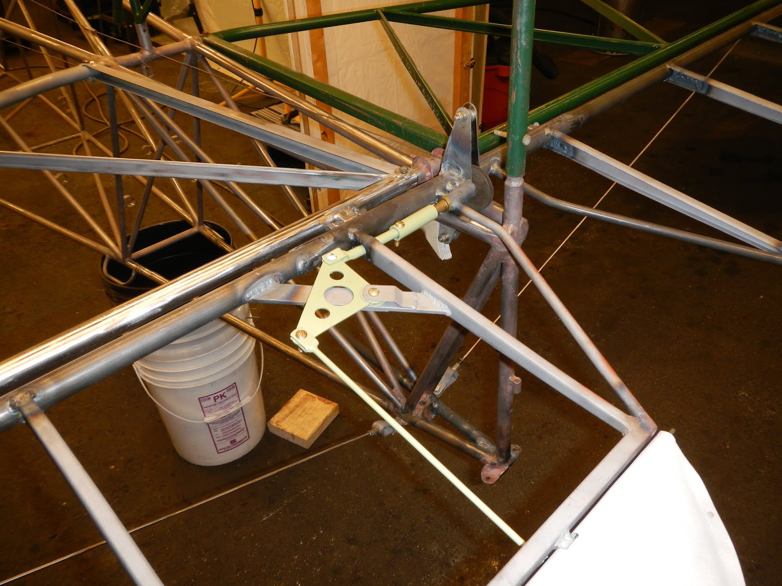
While
things were together, I also temporarily installed the trim system and
identified several items needing attention

The trim horn had been repaired with a doubler, and drilled to -4 and it was worn beyond that

The clevis on the pushrod was also replaced

I found a nylon washer that was the perfect thickness to eliminate the free play.

The crank handle rollpin hole is relocated 90 degrees and the Tcraft gets treated to a couple of DC-8 thrust reverser bushings so, for a while at least, the trim crank handle won't have the usual floppy feel.

One of the spot welds had popped on the tab and a small crack occurred at that location. One 3/32 rivet was added and PRC was used for additional bonding.
I formed an eye on the end of the hinge pin with the idea that it will be both stronger for the cotter pin retention method and easier to remove.


upper and lower bronze bushings replaced

but this did not solve the up and down free play

the lower rudder hinge halves were also worn so I cut them off and welded on new. Now the rudder is nice and snug in all directions

New tailwheel crank drilled after welding washers on to repair the elongated holes

No comments:
Post a Comment